
Arduino with Atmega328p and FTDI
Created a PCB design for an Arduino with ATmega328P and FTDI by integrating the microcontroller, USB-to-serial converter, and supporting components. Begin by placing the ATmega328P, proper spacing and orientation is ensured. Connected the VCC and GND pins to power and ground planes, respectively. Added decoupling capacitors near the microcontroller to stabilize power supply.
Incorporated the FTDI for USB communication. Connected its TX and RX pins to ATmega328P's RX and TX pins, respectively. Also included a 6-pin header for FTDI programming and debugging. I also integrated a 16MHz crystal oscillator and load capacitors for the ATmega328P to ensure accurate clocking.
Incorporated pull-up resistors for the reset and serial programming lines. And a capacitor is added to the reset line for stability. The headers are included for external connections, such as digital and analog pins, power sources, and additional peripherals.
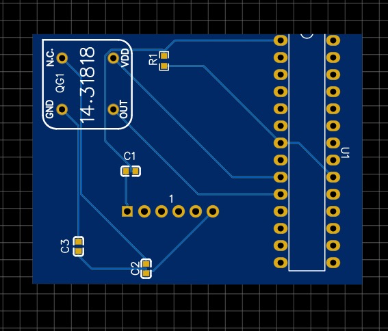
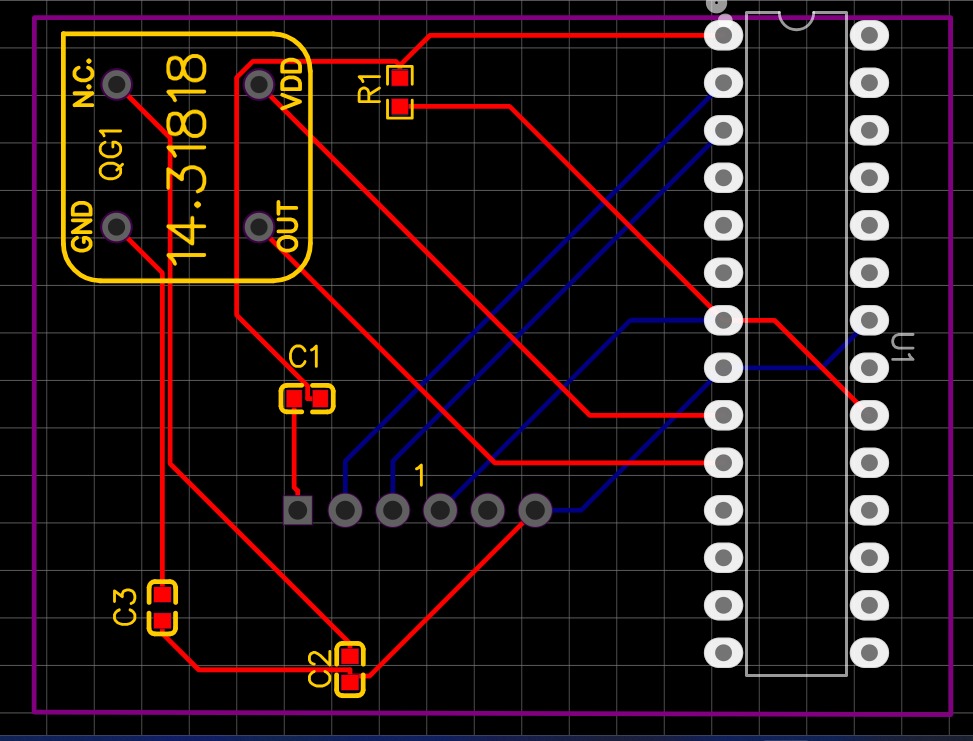
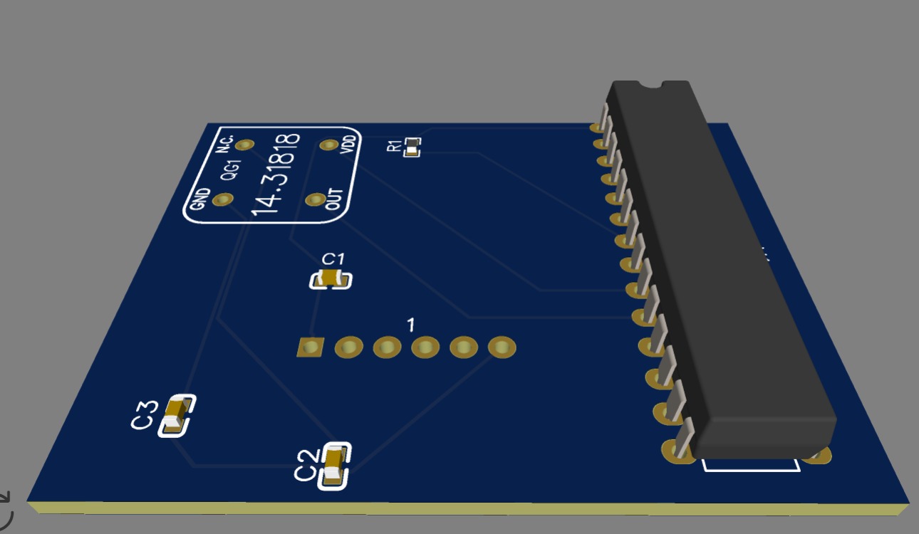
Components are arranged logically, considering proper signal flow and minimizing trace lengths to reduce noise. A ground plane is implemented to enhance signal integrity and minimize interference. Finally, the schematic is converted to PCB design and the components are dragged and dropped in such a way that no two wires are crossed. The converted PCB design is viewed in 2d and 3d models.